The frame can be constructed with Open beams or with V-slot beams. Small changes in brackets are needed for the V-Slot scenario. The Figure shows a frontal view of a version rendered using open beams.
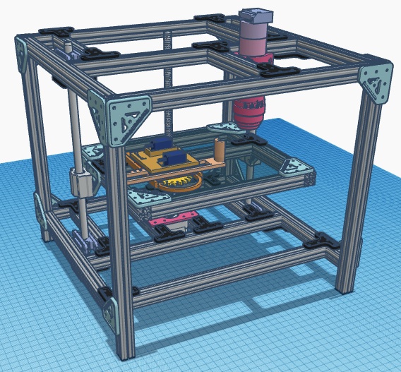
There are three critical mechanical components which are “horizontal”. One corresponds to the Stage itself which is where the XY translation system is mounted and where the sample is located. This Stage, is itself located inside a volume defined by aligning a Top frame and Bottom frame components and joining them “vertically” with four 270 mm beams at the corners; thus making up the main frame of the microscope.
Stage
The Stage corresponds to the platform where the (XY translation) CNC PlotterBot micro robot is placed and modified (hacked) a bit so it can hold a biological sample in a petri dish instead of its originally intended pencil. The Stage is itself a platform that can move up and down along a linear translation axis (Z axis). This movement dimension is what makes possible for the HomeScope to focus the Raspberry Pi camera on the sample held by the PlotterBot.
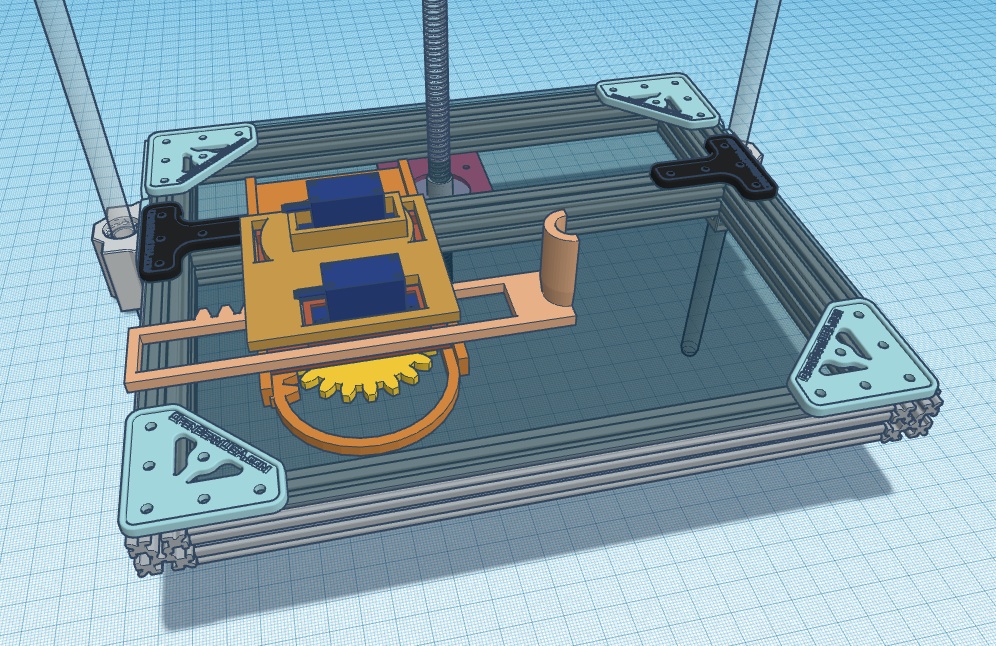
The Stage component is made of five 210 mm beams which hold to each other by two T-brackets and eight L-brackets. Four of these L-brackets hold four of the 210 mm beams into a rectangle shaped area. Four other L-brackets attached to the sides of the Stage are used to hold the linear platforms which travel along the smooth rods on each side in order to implement Z axis translation. A Nema 17 stepper motor bracket (with no motor attached) is used here as a hack to interface the stage with the linear translation axis (lead screw). This bracket is aligned (but rotated 90 degrees) with another Nema 17 bracket located on the Bottom frame component which is the bracket that actually holds the stepper motor powering Z axis translation.
Top frame
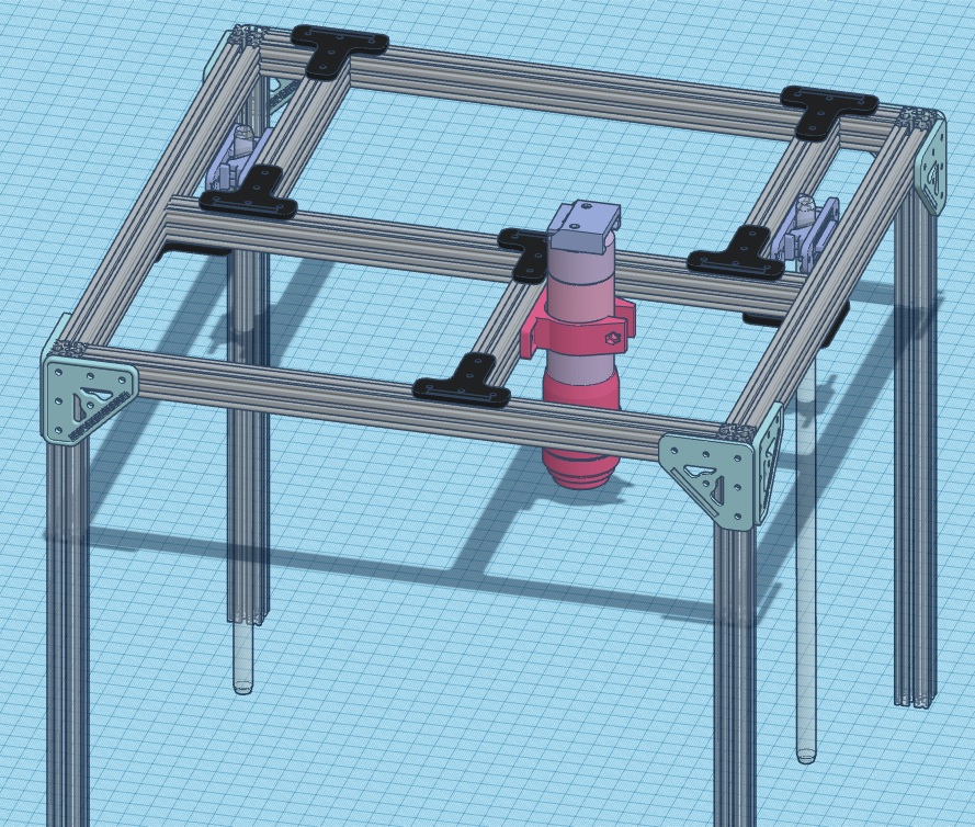
The Top frame is made of five 300 mm beams in addition to two 150 mm beams used to hold two pairs of shaft clamps (i.e. four shaft clamps) holding up the linear rails (smooth rods). These rails are used by a lead screw, located at the center, to guide the Stage up and down the Z-axis. A custom length 125 mm beam (cutted of a 150 mm piece) is used to hold the 3D printed optical clamp from the OpenLabTools microscope which is used to set the optical tube in place. Beams are joined together using eight T-brackets on the inside joints and eight L-brackets on the outer corners. Notice that each of the elements (on the Top frame) that need to be alight with elements on the Bottom frame (left pair clamp, right pair of clamps, and optical system) all can be locally adjusted in the XY directions. These flexibility is needed for an easy assembly of the hole structure when aligning Top frame with Bottom frame and Stage.
Bottom frame
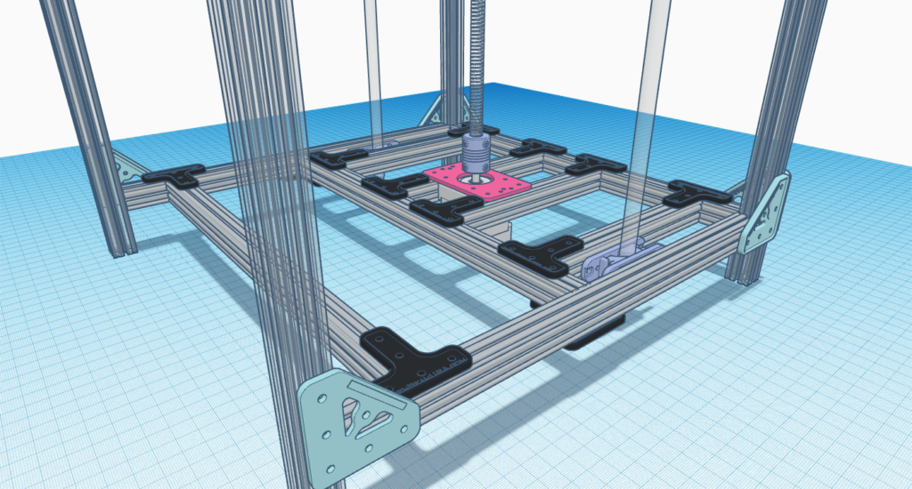
The Bottom frame is similar to the Top frame in that it is also made of five 300 mm beams. The Bottom frame, however uses an extra pair of 150mm beams. The first pair is used to hold the lower end of the smooth rods with a pair of shaft clamp pairs while the extra beams are used to attach a Nema 17 motor bracket (this one indeed host a motor). This bracket, which is located on the Bottom frame, needs to align with the Nema 17 bracket located on of the Stage. These extra beams also need four more T-brackets for their attachment to the group on top of the eight it needs just like its Top counterpart. The union to the vertical beams aligning Top and Bottom frames is done with six L-brackets. Notice that, as before, all attachment points that are needed to align (left pair clamp, right pair of clamps, center lead screw, and Nema bracket); can all move locally in XY directions. Such design consideration is critical for achieving a good frame architecture.