Two-state machine: both Arduinos work as a two-state automata with states: listening and actuating (executing). When in the listening state, Arduino checks for user input via direct interaction with HomeScope (hardware), or by interaction via the Raspberry Pi computer. If while listening any interaction is detected, the system switches to the actuating state. After the execution of the detected command is finished, the system returns to the listening state. Both Arduinos reflect their own state over (output) pin 12 which is LOW when listening and HIGH when actuating. Notice that Arduino logic works at 5 Volts while the Raspberry GPIO pins work at 3.3 Volts. To prevent a disaster we need to use logical convertors (logic level shifters) on each line connecting Arduino and Raspberry Pi pins.
Messaging Protocol
For each degree of motion of HomeScope, X and Y for moving the sample and Z to focus, we have a 2 bit protocol to communicate the movement configuration changes from the Raspberry Pi to the Arduino, so the Arduino controlling that/those degrees of freedom can execute the movement command. The protocol is sketched on the Figure and we will refer to it bellow in detail when talking about each Arduino system; but in general when HomeScope’s XYZ-robot is at rest, each degree of freedom must Stay put. We use a LOW LOW configuration arriving to the Arduino over two input pins; we write this as 00. To move Up and Down the respective axis of motion we use 01 and 10 respectively with 1 representing a HIGH.
Arduino Z
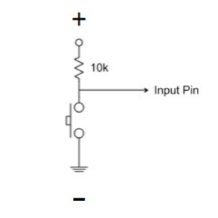
Arduino Z is in charge of moving the microscope’s stage up and down. This is needed so HomeScope can focus it’s image system on a biological texture existing in the biological tissue growing on its culture chamber. A movement instruction might come from an user interacting directly with HomeScope’s push buttons or from the pins bringing movement wishes from the RBPi computer. In the case of direct user interaction, the message is coming over Arduino (input) pin 2; if the user wants to move down, pin 2 gets grounded. Pin 2 is pulled-up so it is always HIGH unless the push button is press down, grounding it for a transient time-scale set by the pull-up resistor (which we physically attach to the push button in hardware). If the pin is LOW, Arduino switches to it’s actuating state to move the stage down. Analogously, if the user wants to move up, Arduino (input) pin 3 is the one that gets grounded and LOW here makes the Arduino to move the stage accordingly.
Another event that makes the Arduino Z switch to its actuating state in order to move the stage, is a Raspberry Pi message being transmitted over Arduino (input) pins 4 and 5, following out custom designed message protocol described above. The code running on this Arduino also checks that HomeScope’s stage is not out of range in the Z axis. To check for this, Arduino (input) pins 6 (bottom) and 7 (top) are connected to end-stop switches which ground the otherwise pulled up (internally by software within the code) pins. Depending on instructions received, the system will tell the stepper motor to step in a given direction over (output) pins 7 and 8 helped by an EasyDriver.
Arduino XY
Arduino XY is in charge of moving the culture chamber around over the Stage surface. This scanning of the sample is possible since this Arduino controls a CNC robot lying on the stage. Arduino XY is listening to the RBPi messages over four pins, two pins for each degree of freedom. To move on the X axis, it listens on Arduino (input) pins 2 and 3, while for Y it listen on Arduino (input) pins 4 and 5. In case a movement message is detected, the Arduino switch its state to actuating and re-write the servo pins accordingly in order to move the corresponding Servo (X or/and Y) to the wished direction. This Arduino is also listening to a Joystick configuration on pins A0 and A1 as well as displaying the servo coordinates on a LCD screen hooked to an i2C controller.
So far we have a very primitive control of the stage so we need to improve. The direction to go is to take advantage of the CNC Tiny robot Arduino code lines to allow HomeScope to understand G-code to control the stage. The current Arduino code here however does not have this functionality.