Using Printed Circuit Boards to build HomeScope saves considerable time. To mount these PCBs to the Frame you cans laser cut our universal PCB holder which works for all the PCBs in this page and our RBPi holder to tight the RBPi to the Frame (pdf dfx/svg)
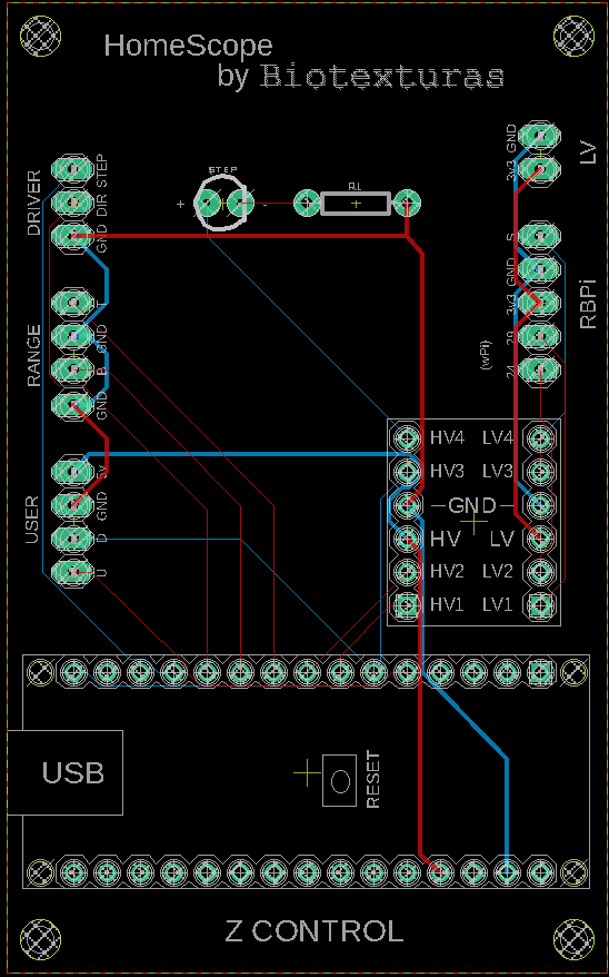
Z control board
To control the focusing system we developed a PCB that host an Arduino Nano (Arduino Z), a LED indicating the state of the two-state automata (off is listening and on is executing), and a logic level convertor. The board can be plugged to the rest of HomeScope boards via 5 sockets of clustered pins. These are:
EasyDriver has 3 pin headers to connect the Z control board to the Motor control board and in this manner send commands from the Arduino Z living on the board. This are correspond to the Arduino ground (GND), a header for the Step command pin, and a header for the Direction (Dir) command.
Range has 4 pin headers to connect to two end switches to prevent the stage from leaving a defined range of movement in the Z axis. The switches, ground the signal pins in case of reaching the range end. Within normal limits the signal is high (~5V). For this the Range header cluster has 4 headers, 2 for ground (GND) and 2 for signals corresponding to Top and Bottom ends of the range.
User / Push Buttons has 4 pin header to connect the board to the front-end interaction board with the buttons to get the stage to move Up and Down. The header cluster also has 2 Arduino grounds to be used by the push down buttons.
RBPi to connect to the Raspberry Pi. These header cluster has 5 header pins to connect to the state signal (S) communicating the state of the on-board two-state Arduino, a Low Voltage ground (GND) and 3.3 V coming from the RBPi which needs to be feed the on-board logical convertor so the y can do the shifting of logic levels.
LV is to split the Low Voltage (3.3 V) from the RBPi and relay it and connect it to he XY control board for the on board logic convertors to do the logic shifting.
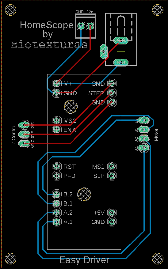
Motor control board
To control a stepper motor via EasyDriver we use an EasyDriver on board as well as two Power plugs (type A and Type B) to access a 12V line and its ground to power the stepper motor responsible for Z movement via the EasyDriver. For logic level shifting the board host 2 logic level convertors. The boas has two clusters of headers.
Motor socket is made of 4 pins and is meant to connect the board to the stepper motor phases. These phases and pins depend on the motor cable color code and should be check for each motor.
Z Control is another cluster of 3 pin headers which works as break through socket for the EasyDriver and it connects the Motor control board to the Z control board to receive Arduino commands.
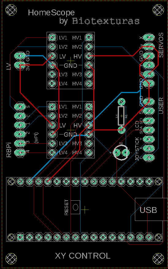
XY control board
To control the XY movement of the servos scanning the sample by controlling a CNC robot. The board host an Arduino Nano (Arduino XY), two logic level shifters, and a LED indicating the state of the Arduino (listening when LED is off and executing when LED is on). The following pin header sockets are present on the board:
LV is to receive the Low Voltage (3V3 and GND) reference for logic shifting on-board. The cables plugging here come from the Z control board which has branch them from the RBPi reference.
Servos are 2 time 3 pin headers which are meant to be routed to the micro-servos powering the CNC robot. Two pins are X and Y pins carrying Arduino signals and the others are 5V and GND.
RBPi is the socket which connects to the Raspberry Pi’s GPIOS. Here we communicate the two-state automata state, over the signal pin (S), to the Pi as well as listen to (XY) movement wishes. Another pin relays the click of the Joystick (C) to the Pi. The socket has 6 header pins, 2 bits per movement plus, signal and plus click.
User is a cluster of header pins which connect GND and 5V on the North pins as well as the i2C pins SCL and SDA for printing into an LCD display as well as 3 more pins for X, Y and C signals of a Joystick for user interaction


